Unbranded Dual Axis Solar Tracker Controller Automatic Tracking & Remote Wind Speed Sensor
Unbranded Dual Axis Solar Tracker Controller Automatic Tracking & Remote Wind Speed Sensor


Unbranded Dual Axis Solar Tracker Controller Automatic Tracking & Remote Wind Speed Sensor
Description
Dual Axis Solar Tracker Controller Automatic Solar Tracking w/ Remote Control Wind Speed Sensor
User Manual of XMYC-3 Solar Tracking Controller:
This controller is a dual-axis sun tracking controller. It uses high-precision inner and outer ring hole sensors to detect the direction of sunlight. Users can analyzes and judges the sensor signal through the single-chip microcomputer circuit on the controller. The corresponding motor on the platform can be controlled through the relay combination on the circuit board to perform the process of tracking the sun. At the same time, you can lay it flat in case of wind (wind speed sensor needs to be purchased), and it can return to the position on cloudy days or nights. English LCD screen is used to display the corresponding parameters, and the parameters can be set by the buttons on the controller or the buttons of an infrared remote control (remote control needs to be purchased).
This controller corresponding platform required to be 2-axis platform, the drive motor of platform is DC brush motor, the motor voltage is 12V or 24V, and current of single motor must be less than 15A (each axis with a 10A fuse by default). Four direction of platform all should have limit switch.
DC IN: 10-28V; DC OUT=DC IN; I MAX. <15A.
Main Components of the Tracking Controller:
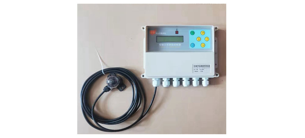
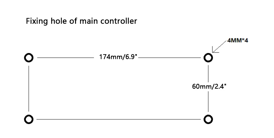
1. Main controller:
Mounting hole of the main controller is 4MM/0.2"; Hole space from left to right is 174MM/6.9". Hole spacing from top to bottom is 60MM/2.4".
It uses a waterproof box as the shell. When installed vertically, it is rain-proof and has up to 6 waterproof outlets for line connection. Terminals are used for wiring on the motherboard. The upper cover has an on-screen display and six operation buttons, which are convenient for users to view parameters and manually operate and set parameters.
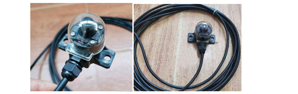
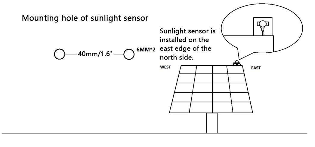
2. Sunlight sensor:
It has a unique deep-hole internal and external inspection method. Through the shield of the pheasant cap in the middle, the voltage of sunlight radiation generated in four directions is transmitted to the motherboard through a 3-meter-long (9.8ft) 5-core cable. The sensor can be fastened with two M6 bolts, 40mm/1.6" apart. It has a transparent cover and has a certain protection against dust and rain.
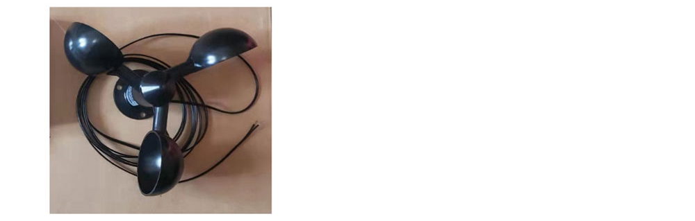
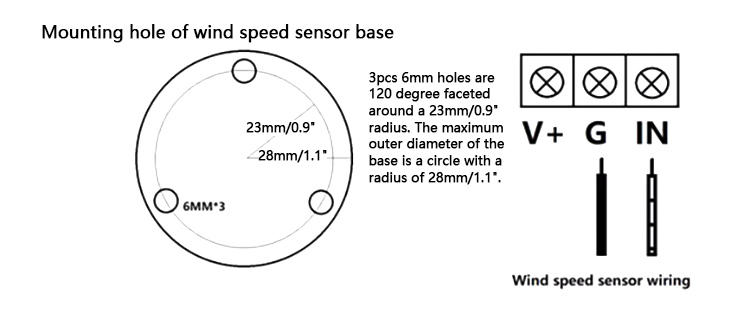
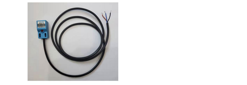
3. Wind speed sensor (optional):
Wind speed sensor is used to detect the wind speed of the environment. When the wind speed reaches the protection value set by the controller, the controller control platform will be driven to a position that can shelter from the wind to protect the platform. The default wind speed sensor has a cable 3 meter/9.8 ft in length. (If you want to configure the wind speed sensor by yourself, a voltage signal type wind speed sensor is needed)
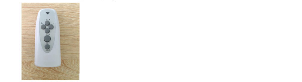
4. IR remote control (optional):
Note: The remote control is powered by 2pcs AAA batteries which are not included in the package.
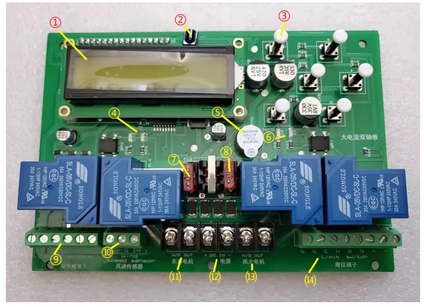
Functions of Controller Board:
1. Display
2. Remote control receiver
3. Operation button
4. East and west axis output indicator light
5. Buzzer
6. South and north axis output indicator light
7. East-west axis fuse
8. South-north axis fuse
9. Sunlight sensor interface (from left to right: ground, east, west, south, north and +)
10. Wind speed sensor interface (from left to right: power supply V+, GND & signal input)
11. East-west axis motor interface
12. Power supply input (DC 12V or 24V. Left is positive end and the right is negative)
13. South-north axis motor interface
14. Limit terminal interface (from left to right: ground, ground, east, west, south, north, + and +)
Installation Method:
Installation of sunlight sensor:
Install the sunlight sensor on the platform plane and follow the platform movements. Note that it is parallel to the flat surface of the platform. Note that it is parallel to the flat surface of the platform. When the platform is erected, the outlet hole on the detection sensor should face underground.
When installed in the northern hemisphere, the detection sensor should be mounted on the east edge of the north side of the platform as much as possible. When installed in the southern hemisphere, the detection sensor should be mounted on the eastern edge of the south side of the platform.
Installation of main controller:
The main control box should be installed near the base post of the platform, and does not need to move with the platform. Try to make sure it's protected from rain, sun and other influences. The outlet hole faces downwards to prevent rainwater from flowing in. The installation should be located in a position which facilitates observation and operation.
Installation of wind speed sensor:
- The wind speed sensor should be installed near the platform, where it can be effectively blown by the wind. Keep away from walls and floors. A column can be used to support and mount the wind speed sensor.
- Wire the wind speed sensor to the main controller according to the mark, leaving room and installing it firmly.
- The wiring method of the wind speed sensor: black wire with white stripes to connect signal input IN, black wire to G, and V+ power supply terminal disconnected.
- If you are using a wind speed sensor from another manufacturers, distinguish the V+, - and signal cable. Wire according to the instructions in the manual. The wind speed sensor terminal V+ on this controller board is the power supply voltage (12-24V). The signal output must be voltage type and the signal range must be less than 5V.
Wiring Method of Limit Switch:
Limit switch is essential. There are A and B methods for position limit as follows (limit switch needs to be purchased separately).
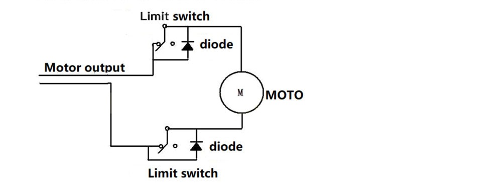
Method A: External limit switch is used. The method of external position limit is to adopt a micro switch with normally closed contact to arrange the four positions that need to be limited on the platform, so as to directly control the power supply circuit of the corresponding motor to achieve the limit. As shown in the figure below:
In this way, it is necessary to pay attention to the sufficient carrying current capacity of the limit switch and the diodes connected in parallel. If a linear actuator with a limit is used, this method is not required, because the linear actuator is equipped with method A limit circuit.
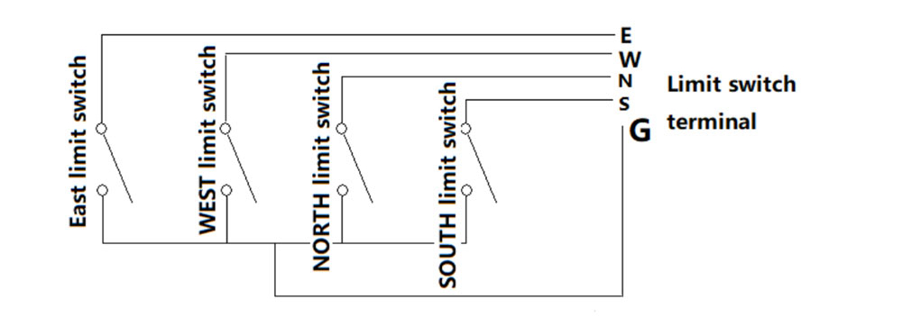
Method B: If the limit signal is introduced into the controller to achieve the limit, a limit switch with normally open contacts is required. When a certain direction reaches the limit, the switch is topped, and the switch will be closed and conducted, and the ground (G) of the limit terminal is shorted with the terminal in the corresponding direction, and the output in this direction will be stopped.
The controller can also be connected to a three-wire NPN proximity switch. When using this kind of switch as a limit, its power supply + end can be connected to the + end of the limit terminal, and the other wiring is the same as that of method B. Note that the top is the sensing area. When there is metal within 5mm, it will output a limit signal.
In the case of separate power supply without connecting to the controller board, the two-axis drive motor should be able to drive the platform to move smoothly within the corresponding range. In this case, the motor can be connected to the motor terminal of the corresponding axis on the control board. Wrong connection of east-west axis motor and north-south axis motor should be avoided.
Running and Debugging:
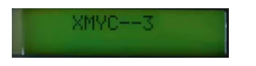
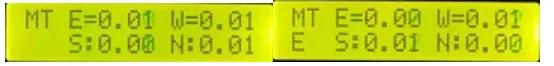
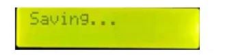
After confirming that the sunlight sensor, wind speed sensor, limit switch, and two-axis motors are connected, a power supply can be connected to the controller board for debugging. The power supply voltage is 12V or 24V (subject to the rated voltage of the motor used). The supply current should be sufficient for the maximum current demand of the two motors. Turn on the power, the buzzer will sound once, at this time the controller should be powered to work, and the screen will display:
The controller then will enter various states based on specific sensor feedback parameters. But at this point, we should first test whether the orientation of the motor is correct. So you have to do manual test first. Press SET button once to enter the following MT page:
At this time, buttons →/←/↓/↑ can control the platform to move east/west/south/north respectively, and the screen will display E/W/S/N. If the movement direction of the platform does not match the direction of manual control, please switch the corresponding wiring. Test the full range of activities of the platform with manual functions, including the limit state function, and test it normally for subsequent work.
When the platform is manually controlled, the corresponding output indicator light on the controller board will be turned on. Press QUIT button to exit the manual mode.
When the button is pressed, the screen background light will be turned on and turned off after 10 seconds. If you press the QUIT button for five seconds, you can turn the background light on or off for a long time.
Parameter Settings:
After making sure that the motor is wired correctly, we then go to the parameter settings and perform the necessary checks and settings on some parameters. In the non-manual control interface, press and hold the SET button for 5 seconds and release it, and the device will enter the parameter setting page. Note that the time parameter is in seconds. The threshold value unit V is voltage volt.
Special note: In the following parameter setting interface, you can switch parameter items by pressing buttons →/←. Press the ↓/↑ button to add/subtract parameters. Press and hold the buttons to quickly add/subtract parameters, and press the QUIT button to exit and save the parameters. In order to facilitate the understanding of the meaning of the parameters, the following parameters are not expressed in order. Please check it by yourself while setting.
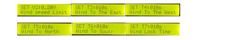
V2/T3/T4/T5/T6/T7 (Wind speed protection related parameters):
When the signal voltage from the wind speed sensor is higher than V2, it will enter the wind speed protection control state, and the order is as follows:
(1) Immediately drive the platform to the east T3 time, and at the same time, execute the platform to the north T5 time
(2) Then the platform is executed to the west T4 time, and at the same time, after the execution of T5 is completed, the platform is executed to the south T6 time.
(3) After performing the above process, T7 is the time to keep locking. During T7 time, the unit remains in standby mode. If the wind speed continues to exceed the V2 value, the T7 time will be full again.
(4) If the wind speed is lower than V2, it will exit the wind speed protection state after the T7 time is over. If it is cloudy during the T7 countdown after the wind speed protection action is completed, the device will also be locked and will not exit the wind speed protection state. The maximum parameter value can be set to 999 and the minimum parameter value can be set to 1. By setting the above parameters reasonably, the platform can be executed to the angle and position desired by the user when the wind speed exceeds the limit. The default configuration of the wind speed sensor signal voltage and wind speed conversion formula: V*25=m/s; V*25=m/sã
For example, the F-number displayed by the wind speed sensor = 0.2 means that the current wind speed is about 5 m/s. If the V2 value is set to 0.18, the wind speed threshold is set to 4.5 m/s.
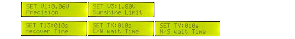
V1/V3/T13/TX/TY parameters:
When the voltage detected by the sunlight sensor in either direction is higher than V3, it will judge that the weather is sunny and it will be timed. If the time that is continuously higher than V3 reaches the T13 time (seconds), it will enter the sunny tracking state. The controller controls the action of each axis motor to align with the sun. V1 is the tracking accuracy, and the smaller the value, the higher the accuracy. However, the mechanical accuracy of the platform is required to reach a certain level. The significance of the TX/TY parameter is that in the process of automatic tracking of the sun, when aiming at the sun, an intermittent time is set to avoid the frequent repetition of the tracking caused by small light changes. That is, after aligning with the sun, the axis enters a sleep time. And then it will re-detect the position of the sun for tracking. The sun also moves very slowly, so setting intervals can also save electricity.
TX: When the east-west axis is aligned, TX is the intermittent waiting time for entry.
TY: When the north-south axis is aligned, TY is the intermittent waiting time for entry.
By setting the above parameters reasonably, you can ensure that the controller can track quickly and accurately on sunny days.
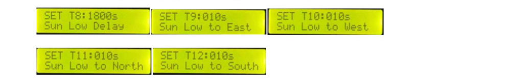
T8/T9/T10/T11/T12 (platform homing parameter setting on cloudy day or at night):
When the voltage in any direction detected by the sunlight detector is lower than V3, the sunlight is judged to be weak. At this point, it will sleep in place and enter the T18 countdown (seconds). During the countdown time, if the sunlight value has not returned above V3, after the countdown ends, it will perform a homing action in the following order:
(1) Run T9 time to the east, and at the same time, run T11 time to the north.
(2) Then execute the T10 time to the west. After the execution of T11 is completed, the T12 time to the south will be executed.
T8 can be set to a maximum of 9990, and other parameter values can be set to a maximum of 999 and a minimum of 1. By setting the above parameters reasonably, the platform can be assigned to the angle or position desired by the user when there is weak sunshine or at night.
After the parameter setting is complete, press the QUIT button to exit and save the parameters.
Logical sequence in which the devices work automatically:
After the device is powered on, the controller will automatically control the data transmitted by the sensor. It is divided into the following cases:
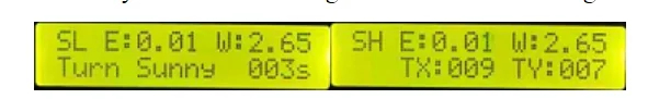
SH: If the voltage detected by the sunlight sensor in any direction is higher than V3, it will enter the sunny day automatic tracking state after accumulating the time set by the timer T13 parameter:
In this state, the controller compares the voltages on the east and west sides and the north and south sides of sunlight sensor to control the platform. When an axis is aligned, it will enter the TX/TY intermittent waiting time. After this time countdown is over, the controller will compare and control again, enabling the tracking process.
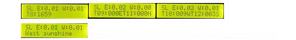
SL: When the voltage detected by the sunlight sensor in any direction is lower than V3, it will enter a cloudy or night state:
First, it goes into the T8 delay. In T8 time, if the voltage is higher than V3, it will exit this state. If the time that continues to be lower than V3 reaches the T8 time, the prescribed action is executed:
After the east T9 time, the west T10 time is executed, and the north T11 time is executed, and then the south T12 time is executed. In this state, the buzzer will sound at a certain frequency to alert. When the action is finished, it will enter the state of waiting for sunlight.
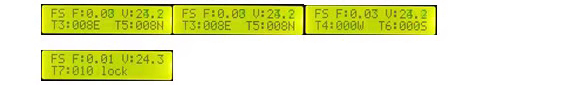
FS: When the wind speed detected by the wind speed sensor is higher than V2, it will enter the wind speed homing state:
When the signal voltage of the wind speed sensor is higher than the set V2 and lasts for 3 seconds, the wind speed is judged to be overrun, and the controller performs the wind speed homing action in the following order:
T3 time to the east, then T4 time to the west, T5 time to the north, and then T6 time to the south. In this state, the buzzer will sound at a certain frequency to alert.
Once the execution is complete, it goes into T7 locking countdown. During the countdown time, if the signal voltage of the wind speed sensor exceeds V2 again, the T7 countdown will be re-timed and it will be locked again. If it's cloudy at this time, it will be locked until sunlight returns.
In the above working state, the screen can display various parameters alternately through buttons →/←: the voltage of the sunshine sensor in the east, west, north and south, the signal voltage of the wind speed sensor, the current power supply voltage, etc.
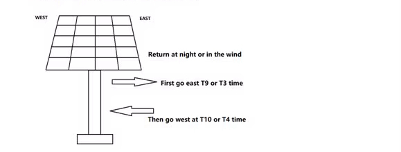
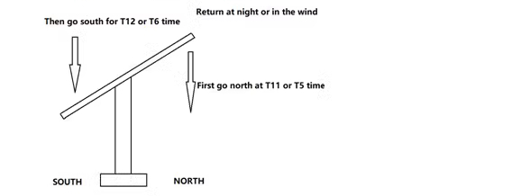
Regarding night homing and windy homing, the sequence logic is as follows:
T9 or T3 to the east and then T10 or T4 to the west:
T11 or T5 to the north, T12 or T6 to the south:
Explanation of the Parameters of LCD screen:
AT: Automatic tracking status. In this state, the device will automatically track the sun.
TX: It is a waiting period when the east-west axis is aligned in the automatic-tracking state. During the period, the device will not operate. Recommendation: 100
TY: It is a waiting period when the north-south axis of the automatic-tracking status is aligned. During the period, the device will not operate. Recommendation: 100
E: East; W: West; S: South; N: North (indicates that the device moves in the corresponding direction)
V: The real-time voltage of power supply.
FS: Wind speed exceeds the set value and it will enter the state of leveling and homing when encountering wind.
FSLOCK: The locked state after the wind speed is reset.
F: Real-time wind speed voltage. The unit is V.
SH: Automatic tracking on sunny days.
MT: Manual operation status. In this state, the 1/2/3/4 buttons of the remote control correspond to manual movement in the north/south/west/east direction.
SL: Weak sunshine. The device will go to sleep and wait for the sunlight to appear again.
T3: The time value in seconds for the device to drive eastward when executing the specified action of wind speed exceeding the limit. The unit is seconds. (Recommended setting value: the time taken by the platform from east to west * 1.2 times)
T4: When performing the specified action of exceeding the wind speed limit, it is the time value of the drive device to the west after T3. The unit is seconds. (Recommended setting: The time it takes for the platform to move from west to east to the east-west axis posture you want the platform to perform)
T5: When performing the specified action of exceeding the wind speed limit, it is the time value of the device to drive north. The unit is seconds. (Recommended setting value: the time taken by the platform from south to north * 1.2 times)
T6: When performing the specified action of exceeding the wind speed limit, T6 is the time value for driving device to the south after T5 time. The unit is seconds. (Recommended setting: the time it takes for the platform to move from north to south to the north-south axis attitude you want the platform to perform)
T7: After performing the specified action of exceeding the wind speed limit, T7 is the self-locking time of the controller. This function is to prevent the wind speed effect from being intermittent and causing the unit to perform frequent tracking. During the self-locking time, if the wind speed exceeds the value again, the time will be immediately re-timed, so that the device does not operate frequently. The unit is seconds. (Recommended setting: 600)
T8: Delay value of weak sunlight duration. (Recommended setting: 1800)
T9: When performing a specified action with weak sunlight, T9 is the time value for the device to drive eastward. The unit is seconds. (Recommended setting value: the time taken by the platform from east to west * 1.2 times)
T10: When performing a specified action with weak sunlight, T10 is the time value for the device to drive to the west after T9. The unit is seconds. (Recommended setting: The time it takes for the platform to move from west to east to the east-west axis posture you want the platform to perform)
T11: It is the time for the device to drive north when performing a specified action with weak sunlight. The unit is seconds. (Recommended setting value: the time taken by the platform from south to north * 1.2 times)
T12: It is the time for the for the device to drive to the south after T11 when performing the specified action in weak sunlight. The unit is seconds. (Recommended setting: the time it takes for the platform to move from north to south to the north-south axis attitude you want the platform to perform)
T13: It is the set continuous delay time for sunlight recovery after the occurrence of weak sunlight. The unit is seconds. (Recommended setting: 10)
V1: Tracking accuracy setting. This value is the voltage value of the tracking accuracy range. When the voltages detected in the east/west and south/north differ by V, the controller believes that the device needs to be moved or aimed at the sun. The smaller the value, the higher the accuracy, and vice versa. It needs to be set according to the characteristics of the platform (Recommended value: 0.06)
V2: Wind speed control voltage. This value is the threshold set by the controller. When the voltage output by the wind speed sensor is higher than this value, the controller deems it necessary to immediately prescribe action to protect the platform (Recommended setting value: The parameter corresponding table of the wind speed sensor shall prevail. The recommended setting value of the sensor configured by our company is 0.15)
V3: Weak sunshine control voltage. It is the threshold value set by the controller. When none of the voltages in the four directions of the sunlight sensor is higher than this value, the controller thinks that the current sunlight is weak and has no power generation value, and cancels tracking. If the device is still tracking the sun on cloudy days, you can turn this value up appropriately so that the controller can judge that it is cloudy. (Recommended setting: 1.80)
Attention:
1. When debugging and operating the platform, personnel should stay away from the platform to avoid accidental injury.
2. Avoid installing, inspecting or debugging equipment during thunderstorms.
3. When wiring, the power supply should be disconnected to avoid short circuit damage to the equipment.
4. The controller should be installed in a location that is protected from the sun and rain and is not easy to be disturbed. The outlet hole is installed facing downward.
5. If the fuse is blown out, it means that the motor may have a high current. A detailed inspection is required before reusing this device.
6. Regularly inspect the sunlight sensor for dirt and for accidental movement.
7. Manually rotate the wind speed sensor regularly for 5 seconds to observe whether the wind speed protection action is normal.
8. When the power supply is insufficient, the controller will restart as soon as the motor outputs. At this time, you should check whether the power supply is insufficient or the motor output is overloaded.
9. When there is smoke and odor, the controller may be irreversibly damaged. Power supply should be cut off immediately, discontinued, and technical support should be sought.
10. When installing outdoors, be sure to pay attention to the upper and lower covers, which should be installed tightly and not leaking. Be careful not to poke the seal off.
Our company reserves the right to change the hardware and software design of this controller without prior notice.
Package Included:
- 1 x Main Controller + Sunshine Sensor
- 1 x Remote Control
- 1 x Wind Speed Sensor
Note:
- Batteries are not included. 2pcs AAA batteries are needed for the remote control.
User Manual of XMYC-3 Solar Tracking Controller:
This controller is a dual-axis sun tracking controller. It uses high-precision inner and outer ring hole sensors to detect the direction of sunlight. Users can analyzes and judges the sensor signal through the single-chip microcomputer circuit on the controller. The corresponding motor on the platform can be controlled through the relay combination on the circuit board to perform the process of tracking the sun. At the same time, you can lay it flat in case of wind (wind speed sensor needs to be purchased), and it can return to the position on cloudy days or nights. English LCD screen is used to display the corresponding parameters, and the parameters can be set by the buttons on the controller or the buttons of an infrared remote control (remote control needs to be purchased).
This controller corresponding platform required to be 2-axis platform, the drive motor of platform is DC brush motor, the motor voltage is 12V or 24V, and current of single motor must be less than 15A (each axis with a 10A fuse by default). Four direction of platform all should have limit switch.
DC IN: 10-28V; DC OUT=DC IN; I MAX. <15A.
Main Components of the Tracking Controller:
1. Main controller:
Mounting hole of the main controller is 4MM/0.2"; Hole space from left to right is 174MM/6.9". Hole spacing from top to bottom is 60MM/2.4".
It uses a waterproof box as the shell. When installed vertically, it is rain-proof and has up to 6 waterproof outlets for line connection. Terminals are used for wiring on the motherboard. The upper cover has an on-screen display and six operation buttons, which are convenient for users to view parameters and manually operate and set parameters.
2. Sunlight sensor:
It has a unique deep-hole internal and external inspection method. Through the shield of the pheasant cap in the middle, the voltage of sunlight radiation generated in four directions is transmitted to the motherboard through a 3-meter-long (9.8ft) 5-core cable. The sensor can be fastened with two M6 bolts, 40mm/1.6" apart. It has a transparent cover and has a certain protection against dust and rain.
3. Wind speed sensor (optional):
Wind speed sensor is used to detect the wind speed of the environment. When the wind speed reaches the protection value set by the controller, the controller control platform will be driven to a position that can shelter from the wind to protect the platform. The default wind speed sensor has a cable 3 meter/9.8 ft in length. (If you want to configure the wind speed sensor by yourself, a voltage signal type wind speed sensor is needed)
4. IR remote control (optional):
Note: The remote control is powered by 2pcs AAA batteries which are not included in the package.
Functions of Controller Board:
1. Display
2. Remote control receiver
3. Operation button
4. East and west axis output indicator light
5. Buzzer
6. South and north axis output indicator light
7. East-west axis fuse
8. South-north axis fuse
9. Sunlight sensor interface (from left to right: ground, east, west, south, north and +)
10. Wind speed sensor interface (from left to right: power supply V+, GND & signal input)
11. East-west axis motor interface
12. Power supply input (DC 12V or 24V. Left is positive end and the right is negative)
13. South-north axis motor interface
14. Limit terminal interface (from left to right: ground, ground, east, west, south, north, + and +)
Installation Method:
Installation of sunlight sensor:
Install the sunlight sensor on the platform plane and follow the platform movements. Note that it is parallel to the flat surface of the platform. Note that it is parallel to the flat surface of the platform. When the platform is erected, the outlet hole on the detection sensor should face underground.
When installed in the northern hemisphere, the detection sensor should be mounted on the east edge of the north side of the platform as much as possible. When installed in the southern hemisphere, the detection sensor should be mounted on the eastern edge of the south side of the platform.
Installation of main controller:
The main control box should be installed near the base post of the platform, and does not need to move with the platform. Try to make sure it's protected from rain, sun and other influences. The outlet hole faces downwards to prevent rainwater from flowing in. The installation should be located in a position which facilitates observation and operation.
Installation of wind speed sensor:
- The wind speed sensor should be installed near the platform, where it can be effectively blown by the wind. Keep away from walls and floors. A column can be used to support and mount the wind speed sensor.
- Wire the wind speed sensor to the main controller according to the mark, leaving room and installing it firmly.
- The wiring method of the wind speed sensor: black wire with white stripes to connect signal input IN, black wire to G, and V+ power supply terminal disconnected.
- If you are using a wind speed sensor from another manufacturers, distinguish the V+, - and signal cable. Wire according to the instructions in the manual. The wind speed sensor terminal V+ on this controller board is the power supply voltage (12-24V). The signal output must be voltage type and the signal range must be less than 5V.
Wiring Method of Limit Switch:
Limit switch is essential. There are A and B methods for position limit as follows (limit switch needs to be purchased separately).
Method A: External limit switch is used. The method of external position limit is to adopt a micro switch with normally closed contact to arrange the four positions that need to be limited on the platform, so as to directly control the power supply circuit of the corresponding motor to achieve the limit. As shown in the figure below:
In this way, it is necessary to pay attention to the sufficient carrying current capacity of the limit switch and the diodes connected in parallel. If a linear actuator with a limit is used, this method is not required, because the linear actuator is equipped with method A limit circuit.
Method B: If the limit signal is introduced into the controller to achieve the limit, a limit switch with normally open contacts is required. When a certain direction reaches the limit, the switch is topped, and the switch will be closed and conducted, and the ground (G) of the limit terminal is shorted with the terminal in the corresponding direction, and the output in this direction will be stopped.
The controller can also be connected to a three-wire NPN proximity switch. When using this kind of switch as a limit, its power supply + end can be connected to the + end of the limit terminal, and the other wiring is the same as that of method B. Note that the top is the sensing area. When there is metal within 5mm, it will output a limit signal.
In the case of separate power supply without connecting to the controller board, the two-axis drive motor should be able to drive the platform to move smoothly within the corresponding range. In this case, the motor can be connected to the motor terminal of the corresponding axis on the control board. Wrong connection of east-west axis motor and north-south axis motor should be avoided.
Running and Debugging:
After confirming that the sunlight sensor, wind speed sensor, limit switch, and two-axis motors are connected, a power supply can be connected to the controller board for debugging. The power supply voltage is 12V or 24V (subject to the rated voltage of the motor used). The supply current should be sufficient for the maximum current demand of the two motors. Turn on the power, the buzzer will sound once, at this time the controller should be powered to work, and the screen will display:
The controller then will enter various states based on specific sensor feedback parameters. But at this point, we should first test whether the orientation of the motor is correct. So you have to do manual test first. Press SET button once to enter the following MT page:
At this time, buttons →/←/↓/↑ can control the platform to move east/west/south/north respectively, and the screen will display E/W/S/N. If the movement direction of the platform does not match the direction of manual control, please switch the corresponding wiring. Test the full range of activities of the platform with manual functions, including the limit state function, and test it normally for subsequent work.
When the platform is manually controlled, the corresponding output indicator light on the controller board will be turned on. Press QUIT button to exit the manual mode.
When the button is pressed, the screen background light will be turned on and turned off after 10 seconds. If you press the QUIT button for five seconds, you can turn the background light on or off for a long time.
Parameter Settings:
After making sure that the motor is wired correctly, we then go to the parameter settings and perform the necessary checks and settings on some parameters. In the non-manual control interface, press and hold the SET button for 5 seconds and release it, and the device will enter the parameter setting page. Note that the time parameter is in seconds. The threshold value unit V is voltage volt.
Special note: In the following parameter setting interface, you can switch parameter items by pressing buttons →/←. Press the ↓/↑ button to add/subtract parameters. Press and hold the buttons to quickly add/subtract parameters, and press the QUIT button to exit and save the parameters. In order to facilitate the understanding of the meaning of the parameters, the following parameters are not expressed in order. Please check it by yourself while setting.
V2/T3/T4/T5/T6/T7 (Wind speed protection related parameters):
When the signal voltage from the wind speed sensor is higher than V2, it will enter the wind speed protection control state, and the order is as follows:
(1) Immediately drive the platform to the east T3 time, and at the same time, execute the platform to the north T5 time
(2) Then the platform is executed to the west T4 time, and at the same time, after the execution of T5 is completed, the platform is executed to the south T6 time.
(3) After performing the above process, T7 is the time to keep locking. During T7 time, the unit remains in standby mode. If the wind speed continues to exceed the V2 value, the T7 time will be full again.
(4) If the wind speed is lower than V2, it will exit the wind speed protection state after the T7 time is over. If it is cloudy during the T7 countdown after the wind speed protection action is completed, the device will also be locked and will not exit the wind speed protection state. The maximum parameter value can be set to 999 and the minimum parameter value can be set to 1. By setting the above parameters reasonably, the platform can be executed to the angle and position desired by the user when the wind speed exceeds the limit. The default configuration of the wind speed sensor signal voltage and wind speed conversion formula: V*25=m/s; V*25=m/sã
For example, the F-number displayed by the wind speed sensor = 0.2 means that the current wind speed is about 5 m/s. If the V2 value is set to 0.18, the wind speed threshold is set to 4.5 m/s.
V1/V3/T13/TX/TY parameters:
When the voltage detected by the sunlight sensor in either direction is higher than V3, it will judge that the weather is sunny and it will be timed. If the time that is continuously higher than V3 reaches the T13 time (seconds), it will enter the sunny tracking state. The controller controls the action of each axis motor to align with the sun. V1 is the tracking accuracy, and the smaller the value, the higher the accuracy. However, the mechanical accuracy of the platform is required to reach a certain level. The significance of the TX/TY parameter is that in the process of automatic tracking of the sun, when aiming at the sun, an intermittent time is set to avoid the frequent repetition of the tracking caused by small light changes. That is, after aligning with the sun, the axis enters a sleep time. And then it will re-detect the position of the sun for tracking. The sun also moves very slowly, so setting intervals can also save electricity.
TX: When the east-west axis is aligned, TX is the intermittent waiting time for entry.
TY: When the north-south axis is aligned, TY is the intermittent waiting time for entry.
By setting the above parameters reasonably, you can ensure that the controller can track quickly and accurately on sunny days.
T8/T9/T10/T11/T12 (platform homing parameter setting on cloudy day or at night):
When the voltage in any direction detected by the sunlight detector is lower than V3, the sunlight is judged to be weak. At this point, it will sleep in place and enter the T18 countdown (seconds). During the countdown time, if the sunlight value has not returned above V3, after the countdown ends, it will perform a homing action in the following order:
(1) Run T9 time to the east, and at the same time, run T11 time to the north.
(2) Then execute the T10 time to the west. After the execution of T11 is completed, the T12 time to the south will be executed.
T8 can be set to a maximum of 9990, and other parameter values can be set to a maximum of 999 and a minimum of 1. By setting the above parameters reasonably, the platform can be assigned to the angle or position desired by the user when there is weak sunshine or at night.
After the parameter setting is complete, press the QUIT button to exit and save the parameters.
Logical sequence in which the devices work automatically:
After the device is powered on, the controller will automatically control the data transmitted by the sensor. It is divided into the following cases:
SH: If the voltage detected by the sunlight sensor in any direction is higher than V3, it will enter the sunny day automatic tracking state after accumulating the time set by the timer T13 parameter:
In this state, the controller compares the voltages on the east and west sides and the north and south sides of sunlight sensor to control the platform. When an axis is aligned, it will enter the TX/TY intermittent waiting time. After this time countdown is over, the controller will compare and control again, enabling the tracking process.
SL: When the voltage detected by the sunlight sensor in any direction is lower than V3, it will enter a cloudy or night state:
First, it goes into the T8 delay. In T8 time, if the voltage is higher than V3, it will exit this state. If the time that continues to be lower than V3 reaches the T8 time, the prescribed action is executed:
After the east T9 time, the west T10 time is executed, and the north T11 time is executed, and then the south T12 time is executed. In this state, the buzzer will sound at a certain frequency to alert. When the action is finished, it will enter the state of waiting for sunlight.
FS: When the wind speed detected by the wind speed sensor is higher than V2, it will enter the wind speed homing state:
When the signal voltage of the wind speed sensor is higher than the set V2 and lasts for 3 seconds, the wind speed is judged to be overrun, and the controller performs the wind speed homing action in the following order:
T3 time to the east, then T4 time to the west, T5 time to the north, and then T6 time to the south. In this state, the buzzer will sound at a certain frequency to alert.
Once the execution is complete, it goes into T7 locking countdown. During the countdown time, if the signal voltage of the wind speed sensor exceeds V2 again, the T7 countdown will be re-timed and it will be locked again. If it's cloudy at this time, it will be locked until sunlight returns.
In the above working state, the screen can display various parameters alternately through buttons →/←: the voltage of the sunshine sensor in the east, west, north and south, the signal voltage of the wind speed sensor, the current power supply voltage, etc.
Regarding night homing and windy homing, the sequence logic is as follows:
T9 or T3 to the east and then T10 or T4 to the west:
T11 or T5 to the north, T12 or T6 to the south:
Explanation of the Parameters of LCD screen:
AT: Automatic tracking status. In this state, the device will automatically track the sun.
TX: It is a waiting period when the east-west axis is aligned in the automatic-tracking state. During the period, the device will not operate. Recommendation: 100
TY: It is a waiting period when the north-south axis of the automatic-tracking status is aligned. During the period, the device will not operate. Recommendation: 100
E: East; W: West; S: South; N: North (indicates that the device moves in the corresponding direction)
V: The real-time voltage of power supply.
FS: Wind speed exceeds the set value and it will enter the state of leveling and homing when encountering wind.
FSLOCK: The locked state after the wind speed is reset.
F: Real-time wind speed voltage. The unit is V.
SH: Automatic tracking on sunny days.
MT: Manual operation status. In this state, the 1/2/3/4 buttons of the remote control correspond to manual movement in the north/south/west/east direction.
SL: Weak sunshine. The device will go to sleep and wait for the sunlight to appear again.
T3: The time value in seconds for the device to drive eastward when executing the specified action of wind speed exceeding the limit. The unit is seconds. (Recommended setting value: the time taken by the platform from east to west * 1.2 times)
T4: When performing the specified action of exceeding the wind speed limit, it is the time value of the drive device to the west after T3. The unit is seconds. (Recommended setting: The time it takes for the platform to move from west to east to the east-west axis posture you want the platform to perform)
T5: When performing the specified action of exceeding the wind speed limit, it is the time value of the device to drive north. The unit is seconds. (Recommended setting value: the time taken by the platform from south to north * 1.2 times)
T6: When performing the specified action of exceeding the wind speed limit, T6 is the time value for driving device to the south after T5 time. The unit is seconds. (Recommended setting: the time it takes for the platform to move from north to south to the north-south axis attitude you want the platform to perform)
T7: After performing the specified action of exceeding the wind speed limit, T7 is the self-locking time of the controller. This function is to prevent the wind speed effect from being intermittent and causing the unit to perform frequent tracking. During the self-locking time, if the wind speed exceeds the value again, the time will be immediately re-timed, so that the device does not operate frequently. The unit is seconds. (Recommended setting: 600)
T8: Delay value of weak sunlight duration. (Recommended setting: 1800)
T9: When performing a specified action with weak sunlight, T9 is the time value for the device to drive eastward. The unit is seconds. (Recommended setting value: the time taken by the platform from east to west * 1.2 times)
T10: When performing a specified action with weak sunlight, T10 is the time value for the device to drive to the west after T9. The unit is seconds. (Recommended setting: The time it takes for the platform to move from west to east to the east-west axis posture you want the platform to perform)
T11: It is the time for the device to drive north when performing a specified action with weak sunlight. The unit is seconds. (Recommended setting value: the time taken by the platform from south to north * 1.2 times)
T12: It is the time for the for the device to drive to the south after T11 when performing the specified action in weak sunlight. The unit is seconds. (Recommended setting: the time it takes for the platform to move from north to south to the north-south axis attitude you want the platform to perform)
T13: It is the set continuous delay time for sunlight recovery after the occurrence of weak sunlight. The unit is seconds. (Recommended setting: 10)
V1: Tracking accuracy setting. This value is the voltage value of the tracking accuracy range. When the voltages detected in the east/west and south/north differ by V, the controller believes that the device needs to be moved or aimed at the sun. The smaller the value, the higher the accuracy, and vice versa. It needs to be set according to the characteristics of the platform (Recommended value: 0.06)
V2: Wind speed control voltage. This value is the threshold set by the controller. When the voltage output by the wind speed sensor is higher than this value, the controller deems it necessary to immediately prescribe action to protect the platform (Recommended setting value: The parameter corresponding table of the wind speed sensor shall prevail. The recommended setting value of the sensor configured by our company is 0.15)
V3: Weak sunshine control voltage. It is the threshold value set by the controller. When none of the voltages in the four directions of the sunlight sensor is higher than this value, the controller thinks that the current sunlight is weak and has no power generation value, and cancels tracking. If the device is still tracking the sun on cloudy days, you can turn this value up appropriately so that the controller can judge that it is cloudy. (Recommended setting: 1.80)
Attention:
1. When debugging and operating the platform, personnel should stay away from the platform to avoid accidental injury.
2. Avoid installing, inspecting or debugging equipment during thunderstorms.
3. When wiring, the power supply should be disconnected to avoid short circuit damage to the equipment.
4. The controller should be installed in a location that is protected from the sun and rain and is not easy to be disturbed. The outlet hole is installed facing downward.
5. If the fuse is blown out, it means that the motor may have a high current. A detailed inspection is required before reusing this device.
6. Regularly inspect the sunlight sensor for dirt and for accidental movement.
7. Manually rotate the wind speed sensor regularly for 5 seconds to observe whether the wind speed protection action is normal.
8. When the power supply is insufficient, the controller will restart as soon as the motor outputs. At this time, you should check whether the power supply is insufficient or the motor output is overloaded.
9. When there is smoke and odor, the controller may be irreversibly damaged. Power supply should be cut off immediately, discontinued, and technical support should be sought.
10. When installing outdoors, be sure to pay attention to the upper and lower covers, which should be installed tightly and not leaking. Be careful not to poke the seal off.
Our company reserves the right to change the hardware and software design of this controller without prior notice.
Package Included:
- 1 x Main Controller + Sunshine Sensor
- 1 x Remote Control
- 1 x Wind Speed Sensor
Note:
- Batteries are not included. 2pcs AAA batteries are needed for the remote control.
Payment Terms
1. We accept PayPal,Payoneer,Visa Card,Google pay,Credit card etc.
2. We ship to your eBay or Paypal address. Please make sure your eBay and Paypal address is correct before you pay.
2. We ship to your eBay or Paypal address. Please make sure your eBay and Paypal address is correct before you pay.
Shipping Terms
1. We will process the order within the handling time ,if you have any questions, please contact us via eBay message or email.
2. For remote regions of DHL/FedEx..., extra shipping costs might be charged. Usually it costs about 30USD-50USD. We will contact you if shipping company informed us your address belongs to remote area. Thanks for your understanding.
2. For remote regions of DHL/FedEx..., extra shipping costs might be charged. Usually it costs about 30USD-50USD. We will contact you if shipping company informed us your address belongs to remote area. Thanks for your understanding.
Return Terms
If you receive the item that not satisfied or defective, please do not open case and kindly notify us within 30 days. We will guide you the returning process for replacement or refund.
Custom Duties & Taxes
1. It is buyer's responsibility to cover the import duties, taxes.We do not charge any taxes and fees, and the possible taxes and fees will be collected by the platform or by third parties such as customs and carriers.
2. Please check with your country's customs office and inform us what/how much should declare before shipping.
2. Please check with your country's customs office and inform us what/how much should declare before shipping.
Feedback
1. Please kindly leave us a positive feedback and 5 star DSR if you satisfied with our product and service. Please feel free to contact us firstly if you have any problem with your order, we are responsible and credible seller and will solve the issue it for you asap.
2. If you are dissatisfied for any reason, please don't be quick to leave us neutral or negative feedback. We work hard to make sure EVERY CUSTOMER 100% SATISFIED and resolve any problem for you and always leave positive feedback to all our customers.
2. If you are dissatisfied for any reason, please don't be quick to leave us neutral or negative feedback. We work hard to make sure EVERY CUSTOMER 100% SATISFIED and resolve any problem for you and always leave positive feedback to all our customers.
On Jan 2, 2024 at 18:59:48 PST, seller added the following information:
| Brand: | Unbranded |
|---|---|
| Isin: | IVJUBLDEOKKF |
This product is not available in the selected country
In Stock
Backordered
Out of Stock


IBspot Buyer Protection
Shop confidently on IBspot, receive your item as described or your money back for eligible orders. Learn Program Terms
GUARANTEED SAFE CHECKOUT
-

MONEY BACK GUARANTEE
30 days money back guarantee, no additional fee charged.
-

EXCELLENT SUPPORT
We provide 24/7 online customer support via email.
-

Fast Shipping
One week domestic shipping. Global delivery to the US in 2 weeks.
Description
Dual Axis Solar Tracker Controller Automatic Solar Tracking w/ Remote Control Wind Speed Sensor
User Manual of XMYC-3 Solar Tracking Controller:
This controller is a dual-axis sun tracking controller. It uses high-precision inner and outer ring hole sensors to detect the direction of sunlight. Users can analyzes and judges the sensor signal through the single-chip microcomputer circuit on the controller. The corresponding motor on the platform can be controlled through the relay combination on the circuit board to perform the process of tracking the sun. At the same time, you can lay it flat in case of wind (wind speed sensor needs to be purchased), and it can return to the position on cloudy days or nights. English LCD screen is used to display the corresponding parameters, and the parameters can be set by the buttons on the controller or the buttons of an infrared remote control (remote control needs to be purchased).
This controller corresponding platform required to be 2-axis platform, the drive motor of platform is DC brush motor, the motor voltage is 12V or 24V, and current of single motor must be less than 15A (each axis with a 10A fuse by default). Four direction of platform all should have limit switch.
DC IN: 10-28V; DC OUT=DC IN; I MAX. <15A.
Main Components of the Tracking Controller:
1. Main controller:
Mounting hole of the main controller is 4MM/0.2"; Hole space from left to right is 174MM/6.9". Hole spacing from top to bottom is 60MM/2.4".
It uses a waterproof box as the shell. When installed vertically, it is rain-proof and has up to 6 waterproof outlets for line connection. Terminals are used for wiring on the motherboard. The upper cover has an on-screen display and six operation buttons, which are convenient for users to view parameters and manually operate and set parameters.
2. Sunlight sensor:
It has a unique deep-hole internal and external inspection method. Through the shield of the pheasant cap in the middle, the voltage of sunlight radiation generated in four directions is transmitted to the motherboard through a 3-meter-long (9.8ft) 5-core cable. The sensor can be fastened with two M6 bolts, 40mm/1.6" apart. It has a transparent cover and has a certain protection against dust and rain.
3. Wind speed sensor (optional):
Wind speed sensor is used to detect the wind speed of the environment. When the wind speed reaches the protection value set by the controller, the controller control platform will be driven to a position that can shelter from the wind to protect the platform. The default wind speed sensor has a cable 3 meter/9.8 ft in length. (If you want to configure the wind speed sensor by yourself, a voltage signal type wind speed sensor is needed)
4. IR remote control (optional):
Note: The remote control is powered by 2pcs AAA batteries which are not included in the package.
Functions of Controller Board:
1. Display
2. Remote control receiver
3. Operation button
4. East and west axis output indicator light
5. Buzzer
6. South and north axis output indicator light
7. East-west axis fuse
8. South-north axis fuse
9. Sunlight sensor interface (from left to right: ground, east, west, south, north and +)
10. Wind speed sensor interface (from left to right: power supply V+, GND & signal input)
11. East-west axis motor interface
12. Power supply input (DC 12V or 24V. Left is positive end and the right is negative)
13. South-north axis motor interface
14. Limit terminal interface (from left to right: ground, ground, east, west, south, north, + and +)
Installation Method:
Installation of sunlight sensor:
Install the sunlight sensor on the platform plane and follow the platform movements. Note that it is parallel to the flat surface of the platform. Note that it is parallel to the flat surface of the platform. When the platform is erected, the outlet hole on the detection sensor should face underground.
When installed in the northern hemisphere, the detection sensor should be mounted on the east edge of the north side of the platform as much as possible. When installed in the southern hemisphere, the detection sensor should be mounted on the eastern edge of the south side of the platform.
Installation of main controller:
The main control box should be installed near the base post of the platform, and does not need to move with the platform. Try to make sure it's protected from rain, sun and other influences. The outlet hole faces downwards to prevent rainwater from flowing in. The installation should be located in a position which facilitates observation and operation.
Installation of wind speed sensor:
- The wind speed sensor should be installed near the platform, where it can be effectively blown by the wind. Keep away from walls and floors. A column can be used to support and mount the wind speed sensor.
- Wire the wind speed sensor to the main controller according to the mark, leaving room and installing it firmly.
- The wiring method of the wind speed sensor: black wire with white stripes to connect signal input IN, black wire to G, and V+ power supply terminal disconnected.
- If you are using a wind speed sensor from another manufacturers, distinguish the V+, - and signal cable. Wire according to the instructions in the manual. The wind speed sensor terminal V+ on this controller board is the power supply voltage (12-24V). The signal output must be voltage type and the signal range must be less than 5V.
Wiring Method of Limit Switch:
Limit switch is essential. There are A and B methods for position limit as follows (limit switch needs to be purchased separately).
Method A: External limit switch is used. The method of external position limit is to adopt a micro switch with normally closed contact to arrange the four positions that need to be limited on the platform, so as to directly control the power supply circuit of the corresponding motor to achieve the limit. As shown in the figure below:
In this way, it is necessary to pay attention to the sufficient carrying current capacity of the limit switch and the diodes connected in parallel. If a linear actuator with a limit is used, this method is not required, because the linear actuator is equipped with method A limit circuit.
Method B: If the limit signal is introduced into the controller to achieve the limit, a limit switch with normally open contacts is required. When a certain direction reaches the limit, the switch is topped, and the switch will be closed and conducted, and the ground (G) of the limit terminal is shorted with the terminal in the corresponding direction, and the output in this direction will be stopped.
The controller can also be connected to a three-wire NPN proximity switch. When using this kind of switch as a limit, its power supply + end can be connected to the + end of the limit terminal, and the other wiring is the same as that of method B. Note that the top is the sensing area. When there is metal within 5mm, it will output a limit signal.
In the case of separate power supply without connecting to the controller board, the two-axis drive motor should be able to drive the platform to move smoothly within the corresponding range. In this case, the motor can be connected to the motor terminal of the corresponding axis on the control board. Wrong connection of east-west axis motor and north-south axis motor should be avoided.
Running and Debugging:
After confirming that the sunlight sensor, wind speed sensor, limit switch, and two-axis motors are connected, a power supply can be connected to the controller board for debugging. The power supply voltage is 12V or 24V (subject to the rated voltage of the motor used). The supply current should be sufficient for the maximum current demand of the two motors. Turn on the power, the buzzer will sound once, at this time the controller should be powered to work, and the screen will display:
The controller then will enter various states based on specific sensor feedback parameters. But at this point, we should first test whether the orientation of the motor is correct. So you have to do manual test first. Press SET button once to enter the following MT page:
At this time, buttons →/←/↓/↑ can control the platform to move east/west/south/north respectively, and the screen will display E/W/S/N. If the movement direction of the platform does not match the direction of manual control, please switch the corresponding wiring. Test the full range of activities of the platform with manual functions, including the limit state function, and test it normally for subsequent work.
When the platform is manually controlled, the corresponding output indicator light on the controller board will be turned on. Press QUIT button to exit the manual mode.
When the button is pressed, the screen background light will be turned on and turned off after 10 seconds. If you press the QUIT button for five seconds, you can turn the background light on or off for a long time.
Parameter Settings:
After making sure that the motor is wired correctly, we then go to the parameter settings and perform the necessary checks and settings on some parameters. In the non-manual control interface, press and hold the SET button for 5 seconds and release it, and the device will enter the parameter setting page. Note that the time parameter is in seconds. The threshold value unit V is voltage volt.
Special note: In the following parameter setting interface, you can switch parameter items by pressing buttons →/←. Press the ↓/↑ button to add/subtract parameters. Press and hold the buttons to quickly add/subtract parameters, and press the QUIT button to exit and save the parameters. In order to facilitate the understanding of the meaning of the parameters, the following parameters are not expressed in order. Please check it by yourself while setting.
V2/T3/T4/T5/T6/T7 (Wind speed protection related parameters):
When the signal voltage from the wind speed sensor is higher than V2, it will enter the wind speed protection control state, and the order is as follows:
(1) Immediately drive the platform to the east T3 time, and at the same time, execute the platform to the north T5 time
(2) Then the platform is executed to the west T4 time, and at the same time, after the execution of T5 is completed, the platform is executed to the south T6 time.
(3) After performing the above process, T7 is the time to keep locking. During T7 time, the unit remains in standby mode. If the wind speed continues to exceed the V2 value, the T7 time will be full again.
(4) If the wind speed is lower than V2, it will exit the wind speed protection state after the T7 time is over. If it is cloudy during the T7 countdown after the wind speed protection action is completed, the device will also be locked and will not exit the wind speed protection state. The maximum parameter value can be set to 999 and the minimum parameter value can be set to 1. By setting the above parameters reasonably, the platform can be executed to the angle and position desired by the user when the wind speed exceeds the limit. The default configuration of the wind speed sensor signal voltage and wind speed conversion formula: V*25=m/s; V*25=m/sã
For example, the F-number displayed by the wind speed sensor = 0.2 means that the current wind speed is about 5 m/s. If the V2 value is set to 0.18, the wind speed threshold is set to 4.5 m/s.
V1/V3/T13/TX/TY parameters:
When the voltage detected by the sunlight sensor in either direction is higher than V3, it will judge that the weather is sunny and it will be timed. If the time that is continuously higher than V3 reaches the T13 time (seconds), it will enter the sunny tracking state. The controller controls the action of each axis motor to align with the sun. V1 is the tracking accuracy, and the smaller the value, the higher the accuracy. However, the mechanical accuracy of the platform is required to reach a certain level. The significance of the TX/TY parameter is that in the process of automatic tracking of the sun, when aiming at the sun, an intermittent time is set to avoid the frequent repetition of the tracking caused by small light changes. That is, after aligning with the sun, the axis enters a sleep time. And then it will re-detect the position of the sun for tracking. The sun also moves very slowly, so setting intervals can also save electricity.
TX: When the east-west axis is aligned, TX is the intermittent waiting time for entry.
TY: When the north-south axis is aligned, TY is the intermittent waiting time for entry.
By setting the above parameters reasonably, you can ensure that the controller can track quickly and accurately on sunny days.
T8/T9/T10/T11/T12 (platform homing parameter setting on cloudy day or at night):
When the voltage in any direction detected by the sunlight detector is lower than V3, the sunlight is judged to be weak. At this point, it will sleep in place and enter the T18 countdown (seconds). During the countdown time, if the sunlight value has not returned above V3, after the countdown ends, it will perform a homing action in the following order:
(1) Run T9 time to the east, and at the same time, run T11 time to the north.
(2) Then execute the T10 time to the west. After the execution of T11 is completed, the T12 time to the south will be executed.
T8 can be set to a maximum of 9990, and other parameter values can be set to a maximum of 999 and a minimum of 1. By setting the above parameters reasonably, the platform can be assigned to the angle or position desired by the user when there is weak sunshine or at night.
After the parameter setting is complete, press the QUIT button to exit and save the parameters.
Logical sequence in which the devices work automatically:
After the device is powered on, the controller will automatically control the data transmitted by the sensor. It is divided into the following cases:
SH: If the voltage detected by the sunlight sensor in any direction is higher than V3, it will enter the sunny day automatic tracking state after accumulating the time set by the timer T13 parameter:
In this state, the controller compares the voltages on the east and west sides and the north and south sides of sunlight sensor to control the platform. When an axis is aligned, it will enter the TX/TY intermittent waiting time. After this time countdown is over, the controller will compare and control again, enabling the tracking process.
SL: When the voltage detected by the sunlight sensor in any direction is lower than V3, it will enter a cloudy or night state:
First, it goes into the T8 delay. In T8 time, if the voltage is higher than V3, it will exit this state. If the time that continues to be lower than V3 reaches the T8 time, the prescribed action is executed:
After the east T9 time, the west T10 time is executed, and the north T11 time is executed, and then the south T12 time is executed. In this state, the buzzer will sound at a certain frequency to alert. When the action is finished, it will enter the state of waiting for sunlight.
FS: When the wind speed detected by the wind speed sensor is higher than V2, it will enter the wind speed homing state:
When the signal voltage of the wind speed sensor is higher than the set V2 and lasts for 3 seconds, the wind speed is judged to be overrun, and the controller performs the wind speed homing action in the following order:
T3 time to the east, then T4 time to the west, T5 time to the north, and then T6 time to the south. In this state, the buzzer will sound at a certain frequency to alert.
Once the execution is complete, it goes into T7 locking countdown. During the countdown time, if the signal voltage of the wind speed sensor exceeds V2 again, the T7 countdown will be re-timed and it will be locked again. If it's cloudy at this time, it will be locked until sunlight returns.
In the above working state, the screen can display various parameters alternately through buttons →/←: the voltage of the sunshine sensor in the east, west, north and south, the signal voltage of the wind speed sensor, the current power supply voltage, etc.
Regarding night homing and windy homing, the sequence logic is as follows:
T9 or T3 to the east and then T10 or T4 to the west:
T11 or T5 to the north, T12 or T6 to the south:
Explanation of the Parameters of LCD screen:
AT: Automatic tracking status. In this state, the device will automatically track the sun.
TX: It is a waiting period when the east-west axis is aligned in the automatic-tracking state. During the period, the device will not operate. Recommendation: 100
TY: It is a waiting period when the north-south axis of the automatic-tracking status is aligned. During the period, the device will not operate. Recommendation: 100
E: East; W: West; S: South; N: North (indicates that the device moves in the corresponding direction)
V: The real-time voltage of power supply.
FS: Wind speed exceeds the set value and it will enter the state of leveling and homing when encountering wind.
FSLOCK: The locked state after the wind speed is reset.
F: Real-time wind speed voltage. The unit is V.
SH: Automatic tracking on sunny days.
MT: Manual operation status. In this state, the 1/2/3/4 buttons of the remote control correspond to manual movement in the north/south/west/east direction.
SL: Weak sunshine. The device will go to sleep and wait for the sunlight to appear again.
T3: The time value in seconds for the device to drive eastward when executing the specified action of wind speed exceeding the limit. The unit is seconds. (Recommended setting value: the time taken by the platform from east to west * 1.2 times)
T4: When performing the specified action of exceeding the wind speed limit, it is the time value of the drive device to the west after T3. The unit is seconds. (Recommended setting: The time it takes for the platform to move from west to east to the east-west axis posture you want the platform to perform)
T5: When performing the specified action of exceeding the wind speed limit, it is the time value of the device to drive north. The unit is seconds. (Recommended setting value: the time taken by the platform from south to north * 1.2 times)
T6: When performing the specified action of exceeding the wind speed limit, T6 is the time value for driving device to the south after T5 time. The unit is seconds. (Recommended setting: the time it takes for the platform to move from north to south to the north-south axis attitude you want the platform to perform)
T7: After performing the specified action of exceeding the wind speed limit, T7 is the self-locking time of the controller. This function is to prevent the wind speed effect from being intermittent and causing the unit to perform frequent tracking. During the self-locking time, if the wind speed exceeds the value again, the time will be immediately re-timed, so that the device does not operate frequently. The unit is seconds. (Recommended setting: 600)
T8: Delay value of weak sunlight duration. (Recommended setting: 1800)
T9: When performing a specified action with weak sunlight, T9 is the time value for the device to drive eastward. The unit is seconds. (Recommended setting value: the time taken by the platform from east to west * 1.2 times)
T10: When performing a specified action with weak sunlight, T10 is the time value for the device to drive to the west after T9. The unit is seconds. (Recommended setting: The time it takes for the platform to move from west to east to the east-west axis posture you want the platform to perform)
T11: It is the time for the device to drive north when performing a specified action with weak sunlight. The unit is seconds. (Recommended setting value: the time taken by the platform from south to north * 1.2 times)
T12: It is the time for the for the device to drive to the south after T11 when performing the specified action in weak sunlight. The unit is seconds. (Recommended setting: the time it takes for the platform to move from north to south to the north-south axis attitude you want the platform to perform)
T13: It is the set continuous delay time for sunlight recovery after the occurrence of weak sunlight. The unit is seconds. (Recommended setting: 10)
V1: Tracking accuracy setting. This value is the voltage value of the tracking accuracy range. When the voltages detected in the east/west and south/north differ by V, the controller believes that the device needs to be moved or aimed at the sun. The smaller the value, the higher the accuracy, and vice versa. It needs to be set according to the characteristics of the platform (Recommended value: 0.06)
V2: Wind speed control voltage. This value is the threshold set by the controller. When the voltage output by the wind speed sensor is higher than this value, the controller deems it necessary to immediately prescribe action to protect the platform (Recommended setting value: The parameter corresponding table of the wind speed sensor shall prevail. The recommended setting value of the sensor configured by our company is 0.15)
V3: Weak sunshine control voltage. It is the threshold value set by the controller. When none of the voltages in the four directions of the sunlight sensor is higher than this value, the controller thinks that the current sunlight is weak and has no power generation value, and cancels tracking. If the device is still tracking the sun on cloudy days, you can turn this value up appropriately so that the controller can judge that it is cloudy. (Recommended setting: 1.80)
Attention:
1. When debugging and operating the platform, personnel should stay away from the platform to avoid accidental injury.
2. Avoid installing, inspecting or debugging equipment during thunderstorms.
3. When wiring, the power supply should be disconnected to avoid short circuit damage to the equipment.
4. The controller should be installed in a location that is protected from the sun and rain and is not easy to be disturbed. The outlet hole is installed facing downward.
5. If the fuse is blown out, it means that the motor may have a high current. A detailed inspection is required before reusing this device.
6. Regularly inspect the sunlight sensor for dirt and for accidental movement.
7. Manually rotate the wind speed sensor regularly for 5 seconds to observe whether the wind speed protection action is normal.
8. When the power supply is insufficient, the controller will restart as soon as the motor outputs. At this time, you should check whether the power supply is insufficient or the motor output is overloaded.
9. When there is smoke and odor, the controller may be irreversibly damaged. Power supply should be cut off immediately, discontinued, and technical support should be sought.
10. When installing outdoors, be sure to pay attention to the upper and lower covers, which should be installed tightly and not leaking. Be careful not to poke the seal off.
Our company reserves the right to change the hardware and software design of this controller without prior notice.
Package Included:
- 1 x Main Controller + Sunshine Sensor
- 1 x Remote Control
- 1 x Wind Speed Sensor
Note:
- Batteries are not included. 2pcs AAA batteries are needed for the remote control.
Payment Terms
1. We accept PayPal,Payoneer,Visa Card,Google pay,Credit card etc.
2. We ship to your eBay or Paypal address. Please make sure your eBay and Paypal address is correct before you pay.
2. We ship to your eBay or Paypal address. Please make sure your eBay and Paypal address is correct before you pay.
Shipping Terms
1. We will process the order within the handling time ,if you have any questions, please contact us via eBay message or email.
2. For remote regions of DHL/FedEx..., extra shipping costs might be charged. Usually it costs about 30USD-50USD. We will contact you if shipping company informed us your address belongs to remote area. Thanks for your understanding.
2. For remote regions of DHL/FedEx..., extra shipping costs might be charged. Usually it costs about 30USD-50USD. We will contact you if shipping company informed us your address belongs to remote area. Thanks for your understanding.
Return Terms
If you receive the item that not satisfied or defective, please do not open case and kindly notify us within 30 days. We will guide you the returning process for replacement or refund.
Custom Duties & Taxes
1. It is buyer's responsibility to cover the import duties, taxes.We do not charge any taxes and fees, and the possible taxes and fees will be collected by the platform or by third parties such as customs and carriers.
2. Please check with your country's customs office and inform us what/how much should declare before shipping.
2. Please check with your country's customs office and inform us what/how much should declare before shipping.
Feedback
1. Please kindly leave us a positive feedback and 5 star DSR if you satisfied with our product and service. Please feel free to contact us firstly if you have any problem with your order, we are responsible and credible seller and will solve the issue it for you asap.
2. If you are dissatisfied for any reason, please don't be quick to leave us neutral or negative feedback. We work hard to make sure EVERY CUSTOMER 100% SATISFIED and resolve any problem for you and always leave positive feedback to all our customers.
2. If you are dissatisfied for any reason, please don't be quick to leave us neutral or negative feedback. We work hard to make sure EVERY CUSTOMER 100% SATISFIED and resolve any problem for you and always leave positive feedback to all our customers.
On Jan 2, 2024 at 18:59:48 PST, seller added the following information:
Shipping Summary:
- Packages are shipped from Monday to Friday.
- The usual time for processing an order is 1 to 3 business days, but may vary depending on the availability of products ordered. This period excludes delivery times, which depend on your geographic location.
- We provide tracking for every order. Tracking will be available once your product is shipped. Each individual product may be shipped from different fulfillment centers across the globe as our product research team spends the time to source quality yet affordable products.
Estimated delivery times:
- Standard Shipping: 3-7 business days
- Expedited Shipping: 2-5 business days
- International Shipping: 10 - 15 business days
Please note that these are estimates, not guarantees. Delivery time depends on a number of variables, and there may be delays such as bad weather affecting air transport, or a package being held for inspection by Customs. ibspot is not liable for any delays in international transportation or customs clearance.
Shipments can be delivered directly to most addresses, except post office boxes. However, in certain remote areas, there may be an additional delivery charge or you may need to pick up your package from the closest service location of ibspot's shipping partner.
Shipping Status:
As soon as your order ships, you'll receive a shipping confirmation email that includes your tracking number.
If you don't receive a shipping confirmation email right away, don't worry! We know the delivery date or date range provided at checkout and we'll be sure to deliver the items within that timeframe.
Order changes:
Please contact our customer support if the order needs to be canceled or modified.
Item not received:
If you've successfully placed an order and haven't received it yet while the tracking status shows it's delivered. you'd wish to contact the carrier to hunt the packages. Once a package is marked “Delivered” by the carrier, we are no longer responsible for lost or stolen items. Please ensure you provide a secure delivery address.
Damaged Parcel
If your package has been delivered in a PO Box, please note that we are not responsible for any damage that may result (consequences of extreme temperatures, theft, etc.).
If you have any questions regarding shipping or want to know about the status of an order, please contact us or email to support@ibspot.com.
Please Read Our Return & Refund Policy Carefully:
Return:
You may return most items within 30 days of delivery for a full refund.
To be eligible for a return, your item must be unused and in the same condition that you received it. It must also be in the original packaging.
Several types of goods are exempt from being returned. Perishable goods such as food, flowers, newspapers or magazines cannot be returned. We also do not accept products that are intimate or sanitary goods, hazardous materials, or flammable liquids or gases.
Additional non-returnable items:
- Gift cards
- Downloadable software products
- Some health and personal care items
To complete your return, we require a tracking number, which shows the items which you already returned to us.
There are certain situations where only partial refunds are granted (if applicable)
- Book with obvious signs of use
- CD, DVD, VHS tape, software, video game, cassette tape, or vinyl record that has been opened
- Any item not in its original condition, is damaged or missing parts for reasons not due to our error
- Any item that is returned more than 30 days after delivery
Items returned to us as a result of our error will receive a full refund,some returns may be subject to a restocking fee of 7% of the total item price, please contact a customer care team member to see if your return is subject. Returns that arrived on time and were as described are subject to a restocking fee.
Items returned to us that were not the result of our error, including items returned to us due to an invalid or incomplete address, will be refunded the original item price less our standard restocking fees.
You should expect to receive your refund within four weeks of giving your package to the return shipper, however, in many cases you will receive a refund more quickly. This time period includes the transit time for us to receive your return from the shipper (5 to 10 business days), the time it takes us to process your return once we receive it (3 to 5 business days), and the time it takes your bank to process our refund request (5 to 10 business days).
If you need to return an item, please Contact Us with your order number and details about the product you would like to return. We will respond quickly with instructions for how to return items from your order.
Shipping Cost
We'll pay the return shipping costs if the return is a result of our error (you received an incorrect or defective item, etc.). In other cases, you will be responsible for paying for your own shipping costs for returning your item. Shipping costs are non-refundable. If you receive a refund, the cost of return shipping will be deducted from your refund.
Depending on where you live, the time it may take for your exchanged product to reach you, may vary.
If you are shipping an item over $75, you should consider using a trackable shipping service or purchasing shipping insurance. We don’t guarantee that we will receive your returned item.
Refund:
- Purchases may be returned within 30 days of the shipping date for a refund.
- Refund will be issued to your original form of payment.
- Refunds for orders purchased with IBSPOT Gift Cards and/or IBSPOT Notes will be issued as a IBSPOT Gift Card and mailed to the original billing address. Gift cards cannot be redeemed for cash unless required by law.
Refund Processing
• Returns to a IBSPOT store will be refunded to the original form of payment or gift card. • Mail-in returns with our prepaid return label will be refunded back to the original form of payment within 3-5 business days after we receive your return. Please allow 5-7 business days for your return to arrive at our Returns Center.
• Note: It may take a few days until your bank posts the refund to your account.
Claims:
Claims related to the product. Be sure to check the details of your purchase carefully before you make the payment, and check the contents of the package(s) promptly upon receipt. If you have a problem with the product, visit our Support Center to find out about return shipping arrangements.
WHICH CIRCUMSTANCES WE OFFER RETURND & REFUND:
WRONG PRODUCT:
If you discover your order is flawed please contact us Mail: support@ibspot.com. With photos of the wrong product we will providing a return shipping label. Once it is tracking we will ship a replacement a product immediately.
Damages and issues
Please inspect your order upon reception and contact us immediately if the item is defective, damaged or if you receive the wrong item, so that we can evaluate the issue and make it right.
Exceptions / non-returnable items
Certain types of items cannot be returned, like perishable goods (such as food, flowers, or plants), custom products (such as special orders or personalized items), and personal care goods (such as beauty products). We also do not accept returns for hazardous materials, flammable liquids, or gases. Please get in touch if you have questions or concerns about your specific item. Unfortunately, we cannot accept returns on sale items or gift cards.
Exchanges
The fastest way to ensure you get what you want is to return the item you have, and once the return is accepted, make a separate purchase for the new item.
Oops!
Sorry, it looks like some products are not available in selected quantity.